Z E M C H 2 0 1 2 I n t e r n a t i o n a l C o n f e r e n c e
714
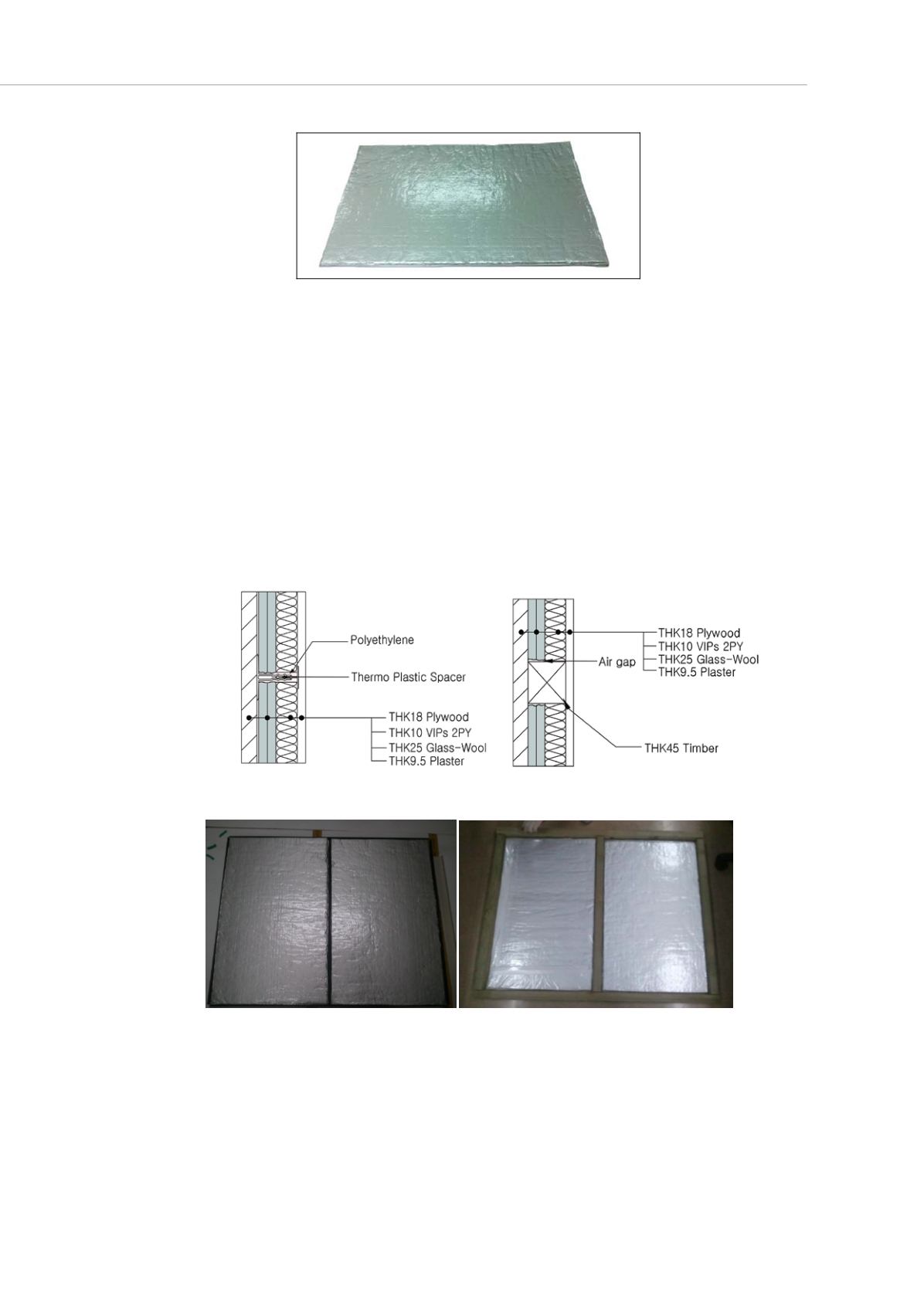
Figure 3: Vacuum insulation panel(VIP)
Two installation methods of VIPs for experimental wall models were considered; joiner
type and wooden lath type.
The composition of the designed wall is as follows; 18 mm of plywood, two layers of 10
mm VIPs, 25 mm of glass wool and the 9.5 mm plaster board. In consideration of the
potential for mechanical damage of the VIPs, the glass wool was placed at the indoor
side of the wall.
Figure 4 illustrates the cross-sectional view of the Joiner type, which uses a
thermoplastic joiner as a spacer and as the attaching material so as to minimize the area
of the thermal bridge. By adding flexible polyethylene to the connecting area, the Joiner
type can minimize the dimensional difference and the air gap. Figure 5 illustrates the
cross-section of the wooden lath type. This type uses wooden laths to attach the VIPs as
a spacer. For the measurement of U-value, the test walls with VIPs constructed, joiner
type 1000mm * 800mm and wooden lath type 1050 mm * 900mm, are shown in Figure 6.
Figure 4: Joiner type details Figure 5: Wooden lath type details
Figure 6: The VIP walls of the joiner type (left) and the wooden lath type (right)
The two types of VIP wall were tested based on KS F2277: Thermal Insulation-
Determination of Steady-State Thermal Transmission Properties - Calibrated Hot Box
Method. The tests depend upon establishing a heat balance between the metering
chamber and the surrounding environment. These tests are performed using
homogeneous characterization panels, which are instrumented on both sides to
determine the surface temperature difference across them. A schematic drawing of the


