A n E x p e r i m e n t a l P e r f o r m a n c e C o m p a r i s o n o f V I P s W a l l
715
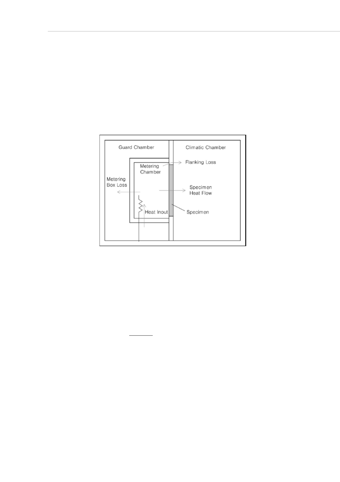
heat flows in a hot box and their sources is shown in Figure 7. For the experiment, the
temperature of guard chamber, metering chamber and climate chamber were set up 20
℃
, 20
℃
and 0
℃
, respectively.
The testing apparatus consisted of a standard calibrated hot box using two chambers of
2700mm×2700mm in symmetrical assembly with a corresponding metering area of
1500mm×1500mm. The hot box (electrically heated) which is metering chamber is
placed between the two chambers (climate and guard chamber), and the test wall is
situated on the one side of hot box. A measurement range of measured heat
transmission coefficient (U-value) is within 5.5
W/(
2
∙ K)
. The accuracy of the U-value
for VIP wall was within 5%.
Figure 7: Schematic drawing of calibrated hot box apparatus
Results and Discussion
From the measurement results such as temperature
( ,
)
and input heat flow
( )
,
the U-value ( ) is calculated by the following equations 1 and 2. The thermal resistance
of the specimen ( ) was calculated as a function of the ratio
( −
)/
, where
, the calibrated heat flow ( ) is determined as the input heat flow by the heater (
Q
)
and heat flow through the test specimen for the calibration ( ), as equation 3.
= ⁄
(1)
=
( − )
∙
(2)
: Thermal resistance of the specimen
[(
2
∙ K)/W]
: Thermal transmission coefficient of the specimen
[W/(
2
∙ K)]
: Hot side air temperature
(℃)
: Cold side air temperature
(℃)
: Metered area of heat flow
(
2
)
= −
(3)
: Calibrated heat flow
(W)
:
Net heat flow added by the heater into the hot box
(W)
Q
: Heat flow through the test specimen for the calibration
(W)


