+ H Y T T E . a V e r s a t i l e C o n s t r u c t i o n S y s t e m
389
Table 2: SIM model adjustments. Variables assumed during the simulations.
unit
M-1
M-2
M-3
U-value wall
W/m
2
K
0.12
0.11
0.11
U-value floor
W/m
2
K
0.12
0.10
0.10
U-value roof
W/m
2
K
0.12
0.10
0.10
U-value windows
W/m
2
K
0.87/0.65
0.72/0.65
0.72/0.65
Air tightness
ach
0.6
0.5
0.5
Glass ratio
%
40
40
20 *
Thermal bridges
W/m
2
K
0.03
0.03
0.03
* Reducing the glass area on the North, East and West façades.
While performing calculations in SIMIEN the respect of minimum requirements for
daylight was verified through the use of ECOTECT in combination with RADIANCE. The
reduction of glass moving from M-2 to M-3 was done intervening on the geometry of the
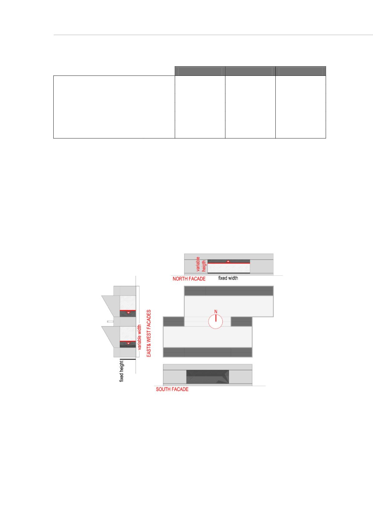
windows on the north, east and west facades. Coherently with the concept’s geometry
variations on the east and west façade were done reducing the width of the window but
still maintaining a constant height of 234,8 cm in order to ensure the exit to the terraces
(fig.4). On the north side instead the height of the window has been assumed as variable
while maintaining constant the width of 540 cm. This was done in order to ensure an
adequate amount of light in the central part of the plan.
Figure 4. Variables assumed for the variation of the glass ratio.
Lighting simulations have been performed under the conditions of uniform sky the day
21
st
of December at 12:00 (winter solstice). Simulations showed that moving from L-1 to
L-2 (fig. X), as a result of the reduced glass ratio, a significant part of the plan does not
reach the required daylight factor of 2%. Different distributions of the glass’ surface have
been thus tested in the L-3 and L-4 models.


